PROFINET Controller Stack
Overview
RAPIDSEA supports PROFINET protocol as a comprehensive IO-Controller implementation. This page explains the controller architecture and details how users should interface the stack with their custom logic to realize PROFINET controller functionality quickly. It also provides guidelines on adopting the stack for different systems.
The PROFINET Controller stack implements all essential protocols:
DCP (Discovery and Configuration Protocol): Device identification and configuration
PN-RPC (PROFINET Remote Procedure Call): Connection establishment and acyclic data exchange
PNIO (PROFINET IO): Cyclic real-time data exchange
Alarm Protocol: Asynchronous event notification and acknowledgment
The below diagram captures the block level diagram of the PROFINET Controller and how it interfaces with other modules.
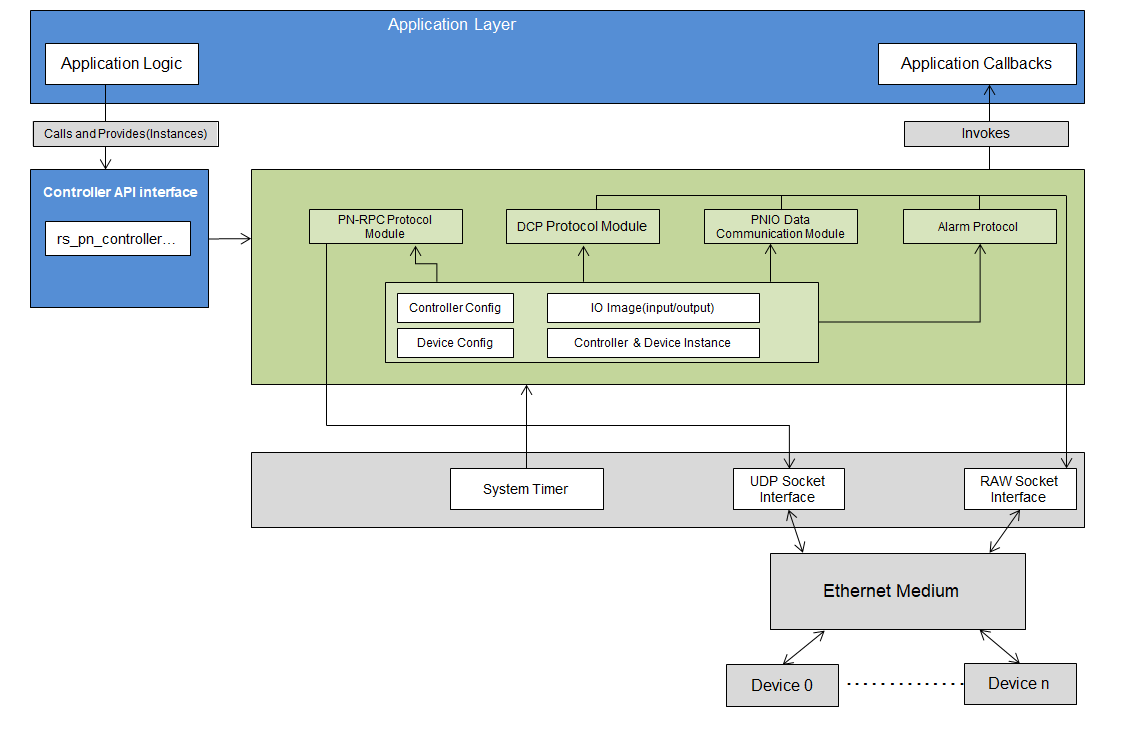
PROFINET Controller Stack Block Diagram
Controller API Interface
The RAPIDSEA PROFINET Controller stack handles protocol-level functionality including device discovery, connection management, cyclic data exchange, and alarm processing.
The below table captures the main functions to be called to drive the stack.
Function |
Description |
|---|---|
rs_pn_controller_open |
Open and initialize the PROFINET controller instance with provided configuration |
rs_pn_controller_close |
Close the PROFINET controller and release associated resources |
rs_pn_controller_process |
Main cyclic processing function; handles PNIO transmission, raw socket reception, and connection management |
rs_pn_controller_send_dcp_command |
Send a DCP command (Identify, Set Name, Set IP, etc.) to a specific device |
rs_pn_controller_connect_device |
Initiate connection to a PROFINET device by sending a Connect Request (AR establishment) |
rs_pn_controller_release_device |
Release connection to a PROFINET device by sending a Release Request |
rs_pn_controller_ping_device |
Ping a PROFINET device to check reachability |
rs_pn_controller_write_pnio_data |
Write data to the PROFINET output IO image for a target address |
rs_pn_controller_read_pnio_data |
Read data from the PROFINET input IO image for a target address |
rs_pn_controller_write_data_record |
Write an acyclic data record to a specific slot/subslot of a PROFINET device |
rs_pn_controller_read_data_record |
Read an acyclic data record from a specific slot/subslot of a PROFINET device |
rs_pn_controller_get_version_info |
Retrieve the version information of the PROFINET Controller module |
Stack Callbacks
The below table lists the callback functions that the caller must implement to receive asynchronous results and events from the stack.
Callback |
Description |
|---|---|
rcb_pn_controller_dcp_identify_result |
Invoked when a DCP Identify All response arrives; provides MAC address and discovery information |
rcb_pn_controller_dcp_get_req_result |
Invoked with the result of a DCP GET request (e.g., Get IP Parameters, Get Station Name) |
rcb_pn_controller_dcp_set_req_result |
Invoked with the result of a DCP SET request (e.g., Set IP Parameters, Set Station Name) |
rcb_pn_controller_dcp_error_callback |
Invoked when a DCP-level error occurs |
rcb_pn_controller_rpc_connection_result |
Invoked when an RPC connection attempt (AR establishment) completes |
rcb_pn_controller_rpc_release_result |
Invoked when an RPC release operation completes |
rcb_pn_controller_rpc_error_callback |
Invoked when an RPC-level error is reported |
rcb_pn_controller_pnio_input_data_changed |
Notification that PNIO input data has changed at the specified IO image offset |
rcb_pn_controller_alarm_callback |
Invoked directly when an alarm notification is received from a device; the stack automatically sends the ACK |
PROFINET Controller Configuration Parameters
Parameter |
Description |
|---|---|
timeout_ms |
General purpose timeout value in milliseconds |
device_port |
Dedicated destination port used by all PROFINET devices for receive |
stn_name / stn_name_len |
Station name of the controller and its length |
ip_addr |
IP address of the controller |
subnet_mask |
Subnet mask of the controller |
gateway |
Default gateway of the controller |
dev_ip_start / dev_ip_end |
IP address range for device discovery |
supported_device_count |
Number of PROFINET devices this controller manages |
device_config |
Array of device configurations (up to |
raw_sock_config |
Raw Ethernet socket configuration (used for PNIO and DCP) |
udp_client_config |
UDP client socket configuration (used for RPC request send and receive response) |
udp_server_tx_config |
UDP server transmit socket configuration (used for RPC response send) |
udp_server_rx_config |
UDP server receive socket configuration (used for RPC request receive) |
ptr_input_io_image |
Pointer to the input IO image buffer |
ptr_output_io_image |
Pointer to the output IO image buffer |
Device Configuration Parameters
Each PROFINET device managed by the controller requires configuration via rs_pn_device_config_t:
Parameter |
Description |
|---|---|
stn_num |
Logical device number |
stn_name |
PROFINET station name (up to 240 characters) |
send_clock_factor |
Send clock factor (multiple of 31.25µs) |
reduction_ratio |
Reduction ratio for the send clock |
rt_class |
Real-Time communication class (e.g., RT_CLASS_1) |
vendor_id |
Device Vendor ID |
device_id |
Device ID |
instance |
Device instance number |
io_frame_type |
Frame type used for IO data exchange (e.g., RTC1, RTC2) |
type |
Type of the device (IO, Drive, Switch) |
startup_mode |
Startup mode: 1 = Legacy, 2 = Advanced |
writeable_im_records |
Writeable IM records for the device |
no_of_modules |
Number of modules in the device |
no_of_sub_modules |
Total number of submodules in the device |
no_of_records |
Total number of parameter records |
module[] |
Array of module configurations ( |
sub_module[] |
Array of submodule configurations ( |
parameter_record[] |
Array of parameter record configurations ( |
input_image_start_offset |
Byte offset of input IO data within the controller’s IO image |
output_image_start_offset |
Byte offset of output IO data within the controller’s IO image |
io_input_data_length |
Length of the input IO data buffer |
io_output_data_length |
Length of the output IO data buffer |
Implementation Guide
This section explains how the PROFINET Controller can be implemented using the RAPIDSEA stack. The stack is available in source form; the steps to be followed are:
Prepare IO Images: Declare static
input_io_image[RS_PN_INPUT_IO_IMAGE_LENGTH]andoutput_io_image[RS_PN_OUTPUT_IO_IMAGE_LENGTH]arrays; assign their pointers inrs_pn_controller_config_tConfigure Controller: Fill
rs_pn_controller_config_t— network interface name (raw_sock_config.iface_name), IP/subnet/gateway, station name, timeout, device port, and device IP scan rangeConfigure Each Device: Populate one
rs_pn_device_config_tper controlled device including its modules, submodules (with IO image offsets), and optional parameter recordsOpen Controller: Call
rs_pn_controller_open()to initialize all communication subsystems; retain the returned handleDevice Discovery Phase: Send
CMD_DCP_IDENTIFY_ALLviars_pn_controller_send_dcp_command(); wait ~2 s for allrcb_pn_controller_dcp_identify_resultcallbacks to arriveConfigure Device Network Parameters: Optionally iterate DCP Set commands (
CMD_DCP_SET_IP_PARAMS,CMD_DCP_SET_STATION_NAME) to assign device identity on the networkConnection Establishment: For each discovered device call
rs_pn_controller_connect_device(); wait for confirmation viarcb_pn_controller_rpc_connection_resultCyclic Processing: Enter the running loop — call
rs_pn_controller_write_pnio_data()/rs_pn_controller_read_pnio_data()for IO data, and callrs_pn_controller_process()on every iterationAlarm Handling: Alarms are delivered directly via
rcb_pn_controller_alarm_callback; no polling or queue management is requiredShutdown Sequence: Call
rs_pn_controller_release_device()for each connected device, thenrs_pn_controller_close()
The high level flow is depicted below:
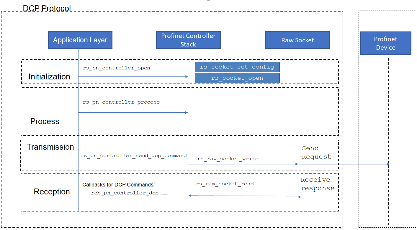
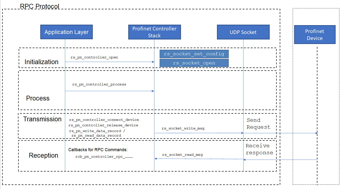
PROFINET Protocol Layers
The PROFINET Controller stack operates across multiple protocol layers:
Real-Time Classes
The stack supports multiple real-time communication classes:
RT_CLASS_1: Standard cyclic real-time communication over Ethernet
Frame ID Ranges
PROFINET uses specific frame ID ranges for different purposes:
Frame ID Range |
Type |
Description |
|---|---|---|
0x0000-0x001F |
Reserved |
Reserved for future use |
0x0020-0x0021 |
PTCP Sync |
Precision Time Protocol synchronization with follow-up |
0x0080-0x0081 |
PTCP Sync |
Precision Time Protocol synchronization without follow-up |
0x0100-0x06FF |
RTC3 |
Real-Time Class 3 (non-redundant, normal or DFP) |
0x0700-0x0FFF |
RTC3 |
Real-Time Class 3 (redundant, normal or DFP) |
0x8000-0xBBFF |
RTC1 Unicast |
Real-Time Class 1 unicast (non-redundant) |
0xBC00-0xBFFF |
RTC1 Multicast |
Real-Time Class 1 multicast (non-redundant) |
0xC000-0xF7FF |
RTC1 Legacy |
Real-Time Class 1 legacy unicast cyclic |
0xF800-0xFBFF |
RTC1 Legacy |
Real-Time Class 1 legacy multicast cyclic |
0xFC01 |
Alarm High |
High-priority alarm frames |
0xFE01 |
Alarm Low |
Low-priority alarm frames |
0xFEFC |
DCP Hello |
DCP hello frames |
0xFEFD |
DCP Get/Set |
DCP get/set parameter frames |
0xFEFE |
DCP Request |
DCP identify multicast request |
0xFEFF |
DCP Response |
DCP identify response |
0xFF00-0xFF01 |
PTCP Announce |
PTCP announcement frames |
0xFF20-0xFF21 |
PTCP Follow-up |
PTCP follow-up frames |
0xFF40-0xFF43 |
PTCP Delay |
PTCP delay measurement frames |
DCP (Discovery and Configuration Protocol)
DCP Commands
The DCP protocol supports the following commands (defined as RS_PN_CMD_DCP_* macros):
Identify Operations:
RS_PN_CMD_DCP_IDENTIFY_ALL (1): Discover all PROFINET devices on the network
RS_PN_CMD_DCP_IDENTIFY_BY_NAME (2): Find a specific device by its station name
Query Operations:
RS_PN_CMD_DCP_GET_IP_PARAMS (3): Query current IP configuration
RS_PN_CMD_DCP_GET_STATION_NAME (4): Retrieve the current station name
Configuration Operations:
RS_PN_CMD_DCP_FLASH_LED (5): Trigger LED flashing for physical device identification
RS_PN_CMD_DCP_SET_IP_PARAMS (6): Configure IP address, subnet mask, and gateway
RS_PN_CMD_DCP_SET_STATION_NAME (7): Assign or change a device’s station name
RS_PN_CMD_DCP_FACTORY_RESET (8): Reset device configuration to factory defaults
DCP Workflow
Call
rs_pn_controller_send_dcp_command()with the desired command and a populatedrs_pn_dcp_req_tThe stack sends the DCP request (multicast for Identify All, unicast for targeted commands)
On response reception, the stack invokes the appropriate callback (
rcb_pn_controller_dcp_identify_result,rcb_pn_controller_dcp_get_req_result, orrcb_pn_controller_dcp_set_req_result)On failure or timeout,
rcb_pn_controller_dcp_error_callbackis invoked
PN-RPC (Remote Procedure Call)
RPC Operations
The PN-RPC protocol handles connection management and acyclic data exchange:
Connection Management:
Connect Request: Establish an Application Relation (AR) with a device via
rs_pn_controller_connect_device()Release Request: Terminate an existing Application Relation via
rs_pn_controller_release_device()
Acyclic Data Exchange:
Read Record: Read an acyclic data record from device via
rs_pn_controller_read_data_record()Write Record: Write an acyclic data record to device via
rs_pn_controller_write_data_record()
Connection Establishment Sequence
The typical connection sequence follows these phases:
Connect Phase:
rs_pn_controller_connect_device()sends a Connect request with AR parametersParameterization Phase: Stack automatically writes configured parameter records to the device
Parameter End: Stack sends PRM_END control command
Application Ready Phase: Exchange APP_READY signals
Data Exchange Phase: Begin cyclic data communication;
rcb_pn_controller_rpc_connection_resultis invoked on completion
PNIO (Cyclic Data Exchange)
IO Image
The controller maintains a flat IO image for all devices:
Input IO Image: Up to
RS_PN_INPUT_IO_IMAGE_LENGTH(4096) bytes; holds data received from all devicesOutput IO Image: Up to
RS_PN_OUTPUT_IO_IMAGE_LENGTH(4096) bytes; holds data to be sent to all devices
Each device’s submodule data is mapped at a specific offset within the IO image using input_image_start_offset and output_image_start_offset in the device configuration.
IO Data Access
The stack accesses IO data using address-based APIs:
Write Output Data:
rs_pn_controller_write_pnio_data(handle, u32_addr, ptr_data, num_bytes, local_iops, ptr_remote_iocs)Read Input Data:
rs_pn_controller_read_pnio_data(handle, u32_addr, ptr_data, ptr_data_len, buffer_len, local_iocs, ptr_remote_iops)
IOPS/IOCS Status Values
Macro |
Value |
Description |
|---|---|---|
RS_PN_PNIO_IOPS_GOOD |
0x80 |
IO Provider Status: data is valid |
RS_PN_PNIO_IOPS_BAD |
0x60 |
IO Provider Status: data is invalid |
RS_PN_PNIO_IOCS_GOOD |
0x80 |
IO Consumer Status: consumer is ready |
RS_PN_PNIO_IOCS_BAD |
0x60 |
IO Consumer Status: consumer is not ready |
Return Codes for PNIO Operations
Macro |
Value |
Description |
|---|---|---|
RS_PN_PNIO_OK |
0 |
Operation successful |
RS_PN_PNIO_INVALID_PARAM |
-1 |
Invalid parameter supplied |
RS_PN_PNIO_ERR_VALUE_LEN |
-2 |
Data length error |
RS_PN_PNIO_UNKNOWN_ADDR |
-3 |
Unknown IO image address |
Module and Submodule Configuration
Each device consists of modules and submodules:
Module Configuration (rs_pn_pnc_mod_data_t):
API identifier (
api)Slot number (
slot)Module identification number (
module_id_num)Module properties (
module_prop)Number of submodules (
no_of_sub_modules)
Submodule Configuration (rs_pn_pnc_submod_data_t):
API, slot, and subslot numbers
Submodule identification number (
submod_id_num)Input/output data lengths (
in_sub_mod_data_length,out_sub_mod_data_length)IOPS/IOCS lengths per direction
Data direction via
sub_mod_propIO image offsets (
input_image_offset,output_image_offset)Pointers to data buffers (
input_data,output_data)
Parameter Record Configuration (rs_pn_parameter_record_t):
Slot and subslot numbers
Record index (
record_index)Data length and pointer (
length,ptr_data)Value constraints:
default_value,min_value,max_value,is_Changeable
Submodule Types
Type |
Description |
|---|---|
RS_PN_SUBMODULE_PROP_TYPE_DAP |
Device Access Point (DAP) — mandatory slot 0 |
RS_PN_SUBMODULE_PROP_TYPE_INPUT |
Input-only submodule (data flows from device to controller) |
RS_PN_SUBMODULE_PROP_TYPE_OUTPUT |
Output-only submodule (data flows from controller to device) |
RS_PN_SUBMODULE_PROP_TYPE_IO |
Bidirectional submodule (both input and output data) |
Alarm Protocol
Alarm Types
PROFINET alarms provide asynchronous event notification:
Diagnosis Alarms: Report diagnostic events from devices
Process Alarms: Indicate process-related events
Pull/Plug Alarms: Notify about module removal/insertion
Status Alarms: Report status changes
Update Alarms: Indicate configuration updates
Redundancy Alarms: Report redundancy-related events
Controlled by Supervisor: Special alarm management
Released: Alarm release notifications
Port Data Change Notification: Network topology changes
Alarm Handling
Alarms are delivered directly to the caller via the rcb_pn_controller_alarm_callback callback — there is no queue to poll. The stack handles the full alarm lifecycle internally:
Alarm Reception: Device sends an alarm notification frame (high-priority on Frame ID 0xFC01, low-priority on 0xFE01)
Immediate Callback: Stack parses the frame and invokes
rcb_pn_controller_alarm_callbackdirectly with the alarm type, device index, and status bytesAutomatic Acknowledgment: The stack automatically sends the ACK frame back to the device upon callback return
Alarm Frame Types
Macro |
Value |
Description |
|---|---|---|
RS_PN_ALARM_FRAME_ACK |
0 |
Acknowledgment frame sent automatically by the stack |
RS_PN_ALARM_FRAME_DATA |
1 |
Data frame, typically part of a high-priority alarm sequence |
RS_PN_ALARM_FRAME_RAISE |
2 |
Frame to raise a new alarm from controller to device |
RS_PN_ALARM_FRAME_RESPONSE |
3 |
Generic response frame in an alarm sequence |
Alarm Priority Levels
The stack supports two alarm priority levels:
High-priority alarms (Frame ID: 0xFC01)
Low-priority alarms (Frame ID: 0xFE01)
Both priority levels are delivered directly through the same rcb_pn_controller_alarm_callback.
PROFINET Controller Stack Buffer Details
The PROFINET Controller stack maintains dedicated buffers for different communication channels:
Raw Socket Buffers
TX Buffer (
raw_sock_tx_buffer):rs_pn_stream_buffer_tofRS_PN_STREAM_BUFFER_SIZEbytes; used for constructing outgoing DCP and PNIO framesRX Buffer (
raw_sock_rx_buffer):RS_PN_ETH_FRAME_LEN(1514) bytes; holds received raw Ethernet frames
UDP Buffers
TX Buffer (
udp_tx_buffer):rs_pn_stream_buffer_tfor RPC request constructionRX Buffer (
udp_rx_buffer):RS_PN_ETH_FRAME_LENbytes for incoming RPC responses
Alarm Buffers
Alarm RX Buffer Count:
RS_PN_ALARM_RX_BUFFER_COUNT= 6 buffersBuffer Size:
RS_PN_ETH_FRAME_LENbytes per bufferMax Alarm Data Size:
RS_PN_MAX_ALARM_DATA_SIZE= 1440 bytes
Device Management
Max Devices Supported:
RS_PN_DEVICE_MAX= 64Configured Devices:
RS_PN_DEVICE_MAX_COUNT= 2 (user-configurable)Max Slots per Device:
RS_PN_MAX_DEVICE_SLOTS= 256Max Subslots:
RS_PN_MAX_SUBSLOTS= 64Max Modules per Device:
RS_PN_MAX_MODULES_PER_DEVICE= 8Max Submodules per Device:
RS_PN_MAX_SUBMODULES_PER_DEVICE= 32Max Records per Device:
RS_PN_MAX_RECORDS_PER_DEVICE= 128
PROFINET Controller Stack Memory Details
Static Memory Allocations
Structure / Field |
Macro / Size |
Description & Impact |
|---|---|---|
|
Core structure |
Main instance holding socket handles, device list, buffers, and connection info |
|
2 × |
Per-device runtime state including AR info, IOCR layouts, and cycle data |
|
|
Stream buffer for constructing outgoing raw Ethernet frames |
|
1514 bytes |
Buffer for received DCP and PNIO frames |
|
|
Stream buffer for constructing outgoing RPC frames |
|
1514 bytes |
Buffer for received RPC responses |
|
8 × |
Module configuration array per device |
|
32 × |
Submodule configuration array per device; includes IO buffer pointers |
|
128 × |
Parameter record configuration array per device |
|
Per device |
Input and output IOCR data structures containing IO data objects and IOCS objects |
IO Image Buffers |
Up to 4096 bytes each |
Caller-provided input and output IO image buffers |
Dynamic Memory Considerations
The following require dynamic allocation or caller-provided buffers:
IO Image Buffers: Caller must allocate and provide pointers in
rs_pn_controller_config_tSubmodule Data Buffers: Each submodule’s
input_dataandoutput_datapointers must reference valid buffersRecord Data: Caller-allocated data buffers pointed to by
rs_pn_parameter_record_t.ptr_data
Note
All buffer macros (e.g.,
RS_PN_ALARM_RX_BUFFER_COUNT,RS_PN_DEVICE_MAX_COUNT) define compile-time constants affecting static memory footprintIncreasing buffer counts improves communication robustness but increases RAM usage
The number of devices (
RS_PN_DEVICE_MAX_COUNT) significantly impacts memory requirementsEach device’s module/submodule configuration proportionally affects memory consumption
AR (Application Relation) State
The controller tracks the AR establishment state for each device:
Macro |
Value |
Description |
|---|---|---|
RS_PN_AR_NOT_ESTABLISHED |
0x00 |
No Application Relation established |
RS_PN_AR_ESTABLISHMENT_IN_PROGRESS |
0x01 |
AR establishment sequence is in progress |
RS_PN_AR_ESTABLISHED |
0x02 |
AR is fully established; cyclic data exchange active |
Device Status
Status |
Description |
|---|---|
DEVSTAT_init (0) |
Device is initialized but not yet active |
DEVSTAT_active (1) |
Device is connected and in cyclic data exchange |
DEVSTAT_inactive (2) |
Device is connected but not in data exchange |
DEVSTAT_offline (3) |
Device is not reachable or has failed |
DEVSTAT_inactive_offline (4) |
Device was inactive and is now offline |
Implementation Notes
Platform Requirements
Network Interface: Raw socket support (
AF_PACKETon Linux) for DCP and PNIO; UDP sockets for RPCReal-Time Scheduling: Recommended for deterministic cyclic communication
Threading: Support for concurrent alarm processing (
RS_PN_ALARM_THREAD_STACK_SIZE= 128 KB)Timing: Microsecond-precision timers for cycle counter management (max cycle time:
RS_PN_MAX_CYCLE_TIME= 1024)
Error Handling
All API functions return rs_ret_val_t status codes. Asynchronous errors are reported via the error callbacks.
Thread Safety
Socket operations should be protected with appropriate synchronization
Device configuration should be set before calling
rs_pn_controller_open()rs_pn_controller_process()should be called from a single thread
Best Practices
Initialize in Order: Open controller → DCP discover → wait for responses → DCP configure → RPC connect → Cyclic process
Validate Callbacks: Always check the
resultparameter in DCP and RPC callbacks before acting on the resultAdd Discovery Delay: Insert a settling delay (e.g., 2 s via
rs_os_msleep()) after broadcastingRS_PN_CMD_DCP_IDENTIFY_ALLto collect all responses before proceeding to configurationGate Connection on Discovery: Check that the device has been discovered before calling
rs_pn_controller_connect_device()to avoid connecting to a device that has not been foundDrive Process Every Iteration: Call
rs_pn_controller_process()unconditionally on every main-loop iteration, regardless of the current stateCheck IOPS Before Using Input Data: Always verify
iops_status == RS_PN_PNIO_IOPS_GOODbefore acting on data read fromrs_pn_controller_read_pnio_data()Graceful Shutdown: Always call
rs_pn_controller_release_device()for each connected device before callingrs_pn_controller_close()
Dependency
This stack depends on the below RAPIDSEA interfaces that can be obtained or custom implemented:
Example Demo
An example implementation is available along with the release and is described in PROFINET Controller Demo Application. The demo is provided as profinet_controller_demo_app.c and demonstrates a two-device setup with an Advantech ADAM-6100PN and an RT-Labs reference device. It supports optional console-based configuration (PN_CONSOLE_ENABLED) and XML-based device configuration (PN_XML_CONFIG_ENABLED).
PROFINET Controller Header Details
Documentation from the relevant header as follows:
Warning
doxygenfile: Cannot find file “rs_profinet_controller.h