PROFIBUS Slave Stack
Profibus Slave stack Overview
This document describes the PROFIBUS DP Slave stack implementation provided by the RAPIDSEA protocol library. The stack supports PROFIBUS DPV0 cyclic exchange, DPV1 acyclic services, extended diagnostics, alarms, and FDL frame handling over an RS-485 serial transport.
The implementation is organized into an application-facing stack interface, a PROFIBUS DP layer, and a Fieldbus Data Link (FDL) layer. It is designed for embedded systems that require a compact protocol implementation with deterministic processing and low RAM usage.
API Interface
Function |
Description |
|---|---|
|
Initialize and open a PROFIBUS slave instance using the supplied configuration. Returns a handle for subsequent calls. |
|
Execute the periodic PROFIBUS slave stack task. Processes FDL frames, DP state transitions, cyclic and acyclic services, alarms, and timeouts. |
|
Get the major, minor, and build versions of the PROFIBUS slave stack. |
|
Close the PROFIBUS slave instance and release the serial port and associated resources. |
|
Queue an identifier-based diagnostic update for the specified module. |
|
Queue a channel-based diagnostic update for a specific module and channel. |
|
Queue a device-related diagnostic update using the provided diagnostic payload. |
|
Send a PROFIBUS DPV1 alarm to the master with specified type, slot, state, sequence, and payload. |
|
Send a PROFIBUS DPV1 status message to the master with specified type, slot, specifier, and payload. |
Callback Functions
The application must implement callback handlers for asynchronous events and data exchange.
Callback |
Invocation |
|---|---|
|
Called when cyclic output data from the master must be applied to device outputs. |
|
Called when the stack requires the current input data to send back to the master. |
|
Called when a DPV1 alarm acknowledgement is received from the master. |
|
Called for DPV1 write requests from the master to update slave data. |
|
Called for DPV1 read requests from the master to supply slave data. |
|
Called when a DPV1 MS2 initiate request is received. |
|
Called when a DPV1 MS2 abort request is received. |
|
Called after the slave address has been updated by the master. |
|
Called when a check-configuration request is received. |
|
Called when a get-configuration request is received. |
|
Called when a set-parameter request is received. |
|
Called when a get-diagnostic request is received. |
|
Called when a sync global command is received. |
|
Called when an unsync global command is received. |
|
Called when a freeze global command is received. |
|
Called when an unfreeze global command is received. |
|
Called when a clear global command is received. |
Implementation Guide
Populate an
rs_pbs_slave_config_tinstance with serial port, slave address, baud rate, TSDR, I/O sizes, and module identifiers.Call
rs_pbs_slave_open()with a pre-allocatedrs_pbs_slave_instance_tand the configuration pointer.Implement required callback functions for cyclic I/O, acyclic read/write, diagnostics, and control commands.
Call
rs_pbs_slave_process()periodically from the main loop.Monitor the stack for DPV1 alarm and status events, using
rs_pbs_slave_alarm_send()andrs_pbs_slave_status_msg_send()when needed.On shutdown or restart, call
rs_pbs_slave_close()to release FDL serial resources and handle state.
Protocol/Stack Layers
The stack is structured into the following layers:
Application Layer - External configuration and callback integration.
PROFIBUS DP Layer - MS0 (Cyclic Service): Handles standard DPV0 cyclic data exchange between the Class 1 master and slave. It manages parameterization, configuration verification, diagnostics, and continuous input/output data transfer. - MS1 (Acyclic Service - Class 1): Provides acyclic data exchange between the Class 1 master and slave over the active MS0 connection. It supports acyclic read/write requests and alarm/status event reporting. - MS2 (Acyclic Service - Class 2): Provides acyclic communication channels for engineering or diagnostic tools (Class 2 masters). It handles connection establishment, termination, and independent acyclic read/write access to slave parameters and data.
FDL Layer - PROFIBUS frame reception, synchronization, timing, frame parsing, and serial transmit/receive.
Serial / RS-485 Transport - Underlying serial interface managed through
rs_serial_*APIs in the FDL initialization.
Data Flow / Workflow
The stack processes PROFIBUS messages in the following sequence:
rs_pbs_slave_process()callspbs_fdl_service()to progress the FDL state machine.pbs_fdl_service()receives raw serial frames and validates frame length, FCS, addressing, and SAP/SSAP.Valid frames are classified into FDL service types, then mapped to DP service types.
DP services handle cyclic exchange, configuration, diagnostics, or DPV1 acyclic requests.
Application callbacks provide or consume current input/output data and accept control or configuration events.
Responses are serialized and transmitted via the FDL send path.
Watchdog and DPV1 connection timeouts are checked each stack cycle.
The below diagram captures the high level sequence of operations associated with the PROFIBUS slave.
Communication Flow
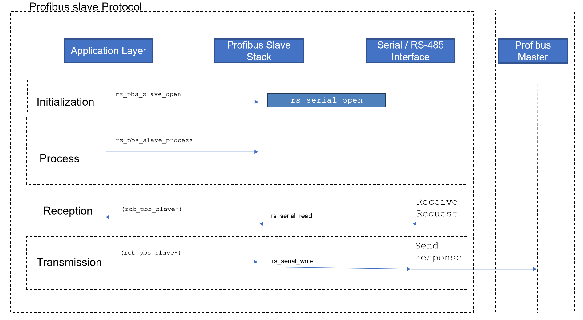
PROFIBUS Communication Flow
Error Handling
The stack uses conservative error detection and recovery:
rs_pbs_slave_open()returns a handle on success and a negative value on failure.rs_pbs_slave_close()returns status after closing the FDL serial interface.rs_pbs_slave_process()ignores invalid handles and does not proceed if the instance is unavailable.The FDL layer validates frame length, SD type, LEr/LE consistency, ED byte, and checksum.
Timeouts trigger FDL error recovery and bus resynchronization.
Invalid or unsupported service frames are rejected and the stack returns to wait state.
Application callbacks should return status codes or lengths consistent with expected data flow based on DPV1 read/write semantics.
Memory / Buffer Details
The PROFIBUS slave stack uses a 4KB memory map and explicit buffer sizing for protocol exchanges.
Region |
Size |
Description |
|---|---|---|
|
64 bytes |
System/header area |
|
4 x 64 bytes |
Identification and maintenance data |
|
128 bytes |
Slave configuration data |
|
244 bytes |
DPV0 set parameter block |
|
244 bytes |
DPV0 check configuration block |
|
6 bytes |
Standard diagnostic request data |
|
244 bytes |
Master-to-slave cyclic output data |
|
244 bytes |
Slave-to-master cyclic input data |
|
238 bytes |
Extended diagnostics area |
|
255 bytes |
DPV1 alarm queue area |
|
64 bytes |
DPV1 status message area |
|
2048 bytes |
DPV1 acyclic data payload |
|
61 bytes |
Future use |
State Machine / States
The stack defines both DP and FDL state machines.
DP Layer States
State |
Description |
|---|---|
|
Initial state after power-on or reset. The slave prepares its internal context and waits to transition to parameterization. |
|
The slave awaits a valid Set_Parameter (Set_Prm) telegram from the master to configure operational parameters. |
|
The slave awaits a Check_Configuration (Chk_Cfg) telegram to verify that its I/O module configuration matches the master’s. |
|
The slave sends diagnostic data (Slave_Diag) to the master, clearing pending startup diagnostics before data exchange. |
|
Normal operational state. The slave cyclically exchanges I/O data and processes acyclic requests and alarms. |
High level state machine of the PROFIBUS DP slave is depicted below.
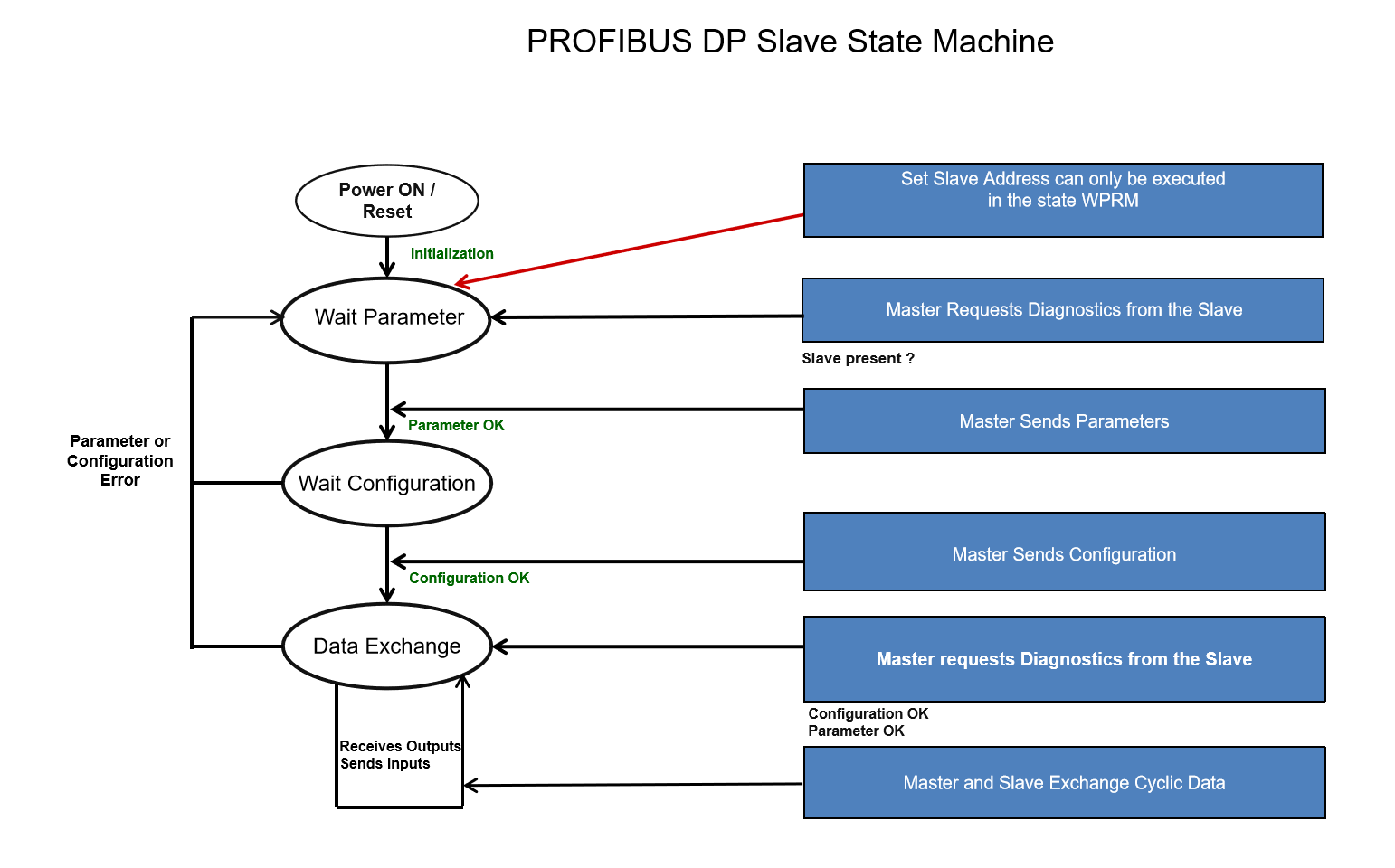
DP Layer State Machine
FDL Layer States
State |
Description |
|---|---|
|
The FDL layer searches for a synchronization period (idle bus time) to align with the bus timing. |
|
The layer waits for the Start Delimiter (SD) of a new incoming frame. |
|
Actively receiving the remaining bytes of the frame based on the parsed length and format. |
|
Validates the received frame (checksum, addressing) and hands it off to the DP layer. |
|
Transmitting a response telegram back onto the serial bus. |
|
Handles serial errors, parity faults, or timeouts, discarding corrupted data and initiating resynchronization. |
Best Practices
Initialize the configuration structure with valid baud rate, TSDR, and module identifiers before calling
rs_pbs_slave_open().Call
rs_pbs_slave_process()from a deterministic periodic task; a millisecond tick is sufficient.Keep serial port access on a single context unless external synchronization is provided.
Provide callbacks for cyclic I/O and diagnostics that execute quickly to preserve real-time behavior.
Do not assume thread safety for the stack handle manager; use external locks if accessing the stack from multiple tasks.
Validate all DPV1 request lengths and return values in callback implementations.
Use the configured
input_lengthandoutput_lengthvalues to size application data buffers.
Dependency
This stack depends on the RAPIDSEA core library and serial interface:
rs_lib.hfor base types and return values.Serial interface APIs:
rs_serial_open(),rs_serial_read(),rs_serial_write(),rs_serial_close(),rs_serial_set_config(),rs_serial_set_inter_char_timeout().Handle manager APIs used by
rs_handle_mgr_get_handle()andrs_handle_mgr_get_info_for_handle().PROFIBUS frame and telegram utilities from
pbs_frame.handpbs_fdl_telegram.h.
Example Demo
An example PROFIBUS Slave implementation is available and is described in PROFIBUS Slave Demo. The demo source is pb_slave_app.c in the apps/profibus_slave_demo_app folder; it demonstrates NVM I&M loading from memory_map.bin, configuration of module IDs (8DI, 8DO, 2AI, 2AO), opening the slave via rs_pbs_slave_open(), and continuous processing with rs_pbs_slave_process(). The demo uses DIP-switch address selection and provides stub callback implementations for DPV1 and diagnostic handling.
PROFIBUS SLAVE Header Details
Documentation from the relevant header as follows:
Warning
doxygenfile: Cannot find file “rs_pbs_slave.h