PROFIBUS Slave Demo
Overview
PROFIBUS DP is a widely used industrial fieldbus communication protocol designed for high-speed cyclic data exchange between automation controllers and distributed field devices. It is extensively used in industrial automation applications such as PLCs, remote I/O systems, drives, sensors, actuators, and process control systems. PROFIBUS DP enables reliable real-time communication between a PROFIBUS master and multiple slave devices in factory and process automation environments.
Embien provides a PROFIBUS DP Slave Stack for implementing PROFIBUS slave functionality in embedded systems. The stack supports cyclic process data communication, acyclic parameter handling, diagnostic services, and standard PROFIBUS DP slave state management. The implementation is designed for easy integration and can be extended through application callbacks and APIs based on system requirements.
The PROFIBUS Slave Demo Application demonstrates the integration of the RAPIDSEA PROFIBUS slave stack APIs in a typical industrial slave device application. The demo simulates digital and analog input/output modules and demonstrates PROFIBUS slave initialization, cyclic input/output data exchange, process data handling, and callback-based PROFIBUS DP service processing.
The application supports a maximum cyclic process data exchange buffer size of 244 bytes for PROFIBUS DP communication. The actual input and output process data size is determined based on the configured module IDs, and only the corresponding input/output data areas are mapped and exchanged during cyclic communication.
Flowchart
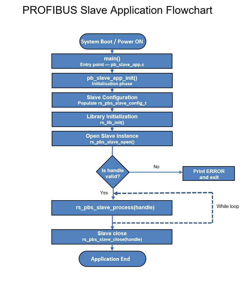
PROFIBUS Slave Application Flow
Supported Functions / Services
Function |
Description |
|---|---|
Set_Slave_Address |
Configuration of slave address via DIP switches or communication |
Diagnostics |
Standard and extended diagnostic data reporting |
Parameterization |
Module parameter configuration and validation |
Configuration |
Slave configuration verification and module setup |
Data_Exchange |
Cyclic exchange of input/output data between master and slave |
Global_Control |
Sync and Freeze commands for synchronous data update |
DPV1 Class 1 Acyclic Read (Input/Output) |
Acyclic read access to input and output data during operation |
DPV1 Class 1 Acyclic Read/Write |
Acyclic read and write access to module or device data |
DPV1 Class 2 Read |
Acyclic read access to device or module data by Class 2 master |
DPV1 Class 2 Write |
Acyclic write access to device or module parameters by Class 2 master |
DPV1 Class 2 Alarm |
Alarm indication from slave to Class 2 master for diagnostics/events |
Application Data Mapping
Input Data Mapping
Offset |
Size |
R/W |
Data |
Type |
Description |
|---|---|---|---|---|---|
0 |
1 |
R |
Digital Input |
uint8_t |
8 digital input channels read via pb_slave_scan_digital_input_value() |
1 |
2 |
R |
Analog Input Channel 0 |
uint16_t |
High byte at offset 1, low byte at offset 2 |
3 |
2 |
R |
Analog Input Channel 1 |
uint16_t |
High byte at offset 3, low byte at offset 4 |
Output Data Mapping
Offset |
Size |
R/W |
Data |
Type |
Description |
|---|---|---|---|---|---|
0 |
1 |
W |
Digital Output |
uint8_t |
8 digital output channels applied bit-wise |
1 |
2 |
W |
Analog Output Channel 0 |
uint16_t |
High byte at offset 1, low byte at offset 2 |
3 |
2 |
W |
Analog Output Channel 1 |
uint16_t |
High byte at offset 3, low byte at offset 4 |
Demo Behavior / Example
The demo application simulates a complete PROFIBUS DP slave with the following behavior:
The following modules are configured for the demo application:
0x10 - 1-byte Digital Input module
0x20 - 1-byte Digital Output module
0x51 - 4-byte Analog Input module (2 x 16-bit channels)
0x61 - 4-byte Analog Output module (2 x 16-bit channels)
Data handling in the demo application:
Digital Input: A 1-byte digital input value is acquired from the hardware through an input callback and transmitted to the master.
Digital Output: A 1-byte digital output value received from the master is applied to the hardware through an output callback.
Analog Input: Two 16-bit analog input values are read from the hardware using an input callback and sent to the master.
Analog Output: Two 16-bit analog output values received from the master are written to the hardware using an output callback.
During cyclic PROFIBUS-DP communication, the slave invokes a callback to acquire input data from the hardware and provides this data to the master. The master sends output data to the slave, which is applied to the hardware through a corresponding output callback.
Addressing / Data Layout
Type |
Description |
|---|---|
Addressing |
The master identifies and accesses the slave data based on the module configuration defined in the GSD file. Each module is mapped using its module ID and slot position, which determines the data structure in the process image. |
Input Buffer |
5 bytes total: 1 byte digital inputs + 4 bytes analog inputs (2 x 16-bit words), arranged contiguously from offset 0 |
Output Buffer |
5 bytes total: 1 byte digital outputs + 4 bytes analog outputs (2 x 16-bit words), arranged contiguously from offset 0 |
Diagnostics Data |
Standard diagnostic data (6 bytes) and extended diagnostics (up to 238 bytes) supported as per PROFIBUS-DP specification |
Application Initialization and Runtime
The demo application starts by calling pb_slave_app_init() from main(). The initialization sequence:
loads I&M and configuration data from
memory_map.bininto a local NVM structure.copies that data into the main slave buffer
pb_slave_buff1.fills the
rs_pbs_slave_config_tinstance with port, baud rate, slave address mode, DPV1 support, module IDs, and I/O lengths.initializes the RAPIDSEA library with
rs_lib_init().opens the PROFIBUS slave instance with
rs_pbs_slave_open().
After initialization, the demo enters a continuous runtime loop where pb_slave_app_task(handle) calls rs_pbs_slave_process(handle) on every iteration.
If rs_pbs_slave_open() fails and returns a negative handle, the demo prints ERROR and exits. The example does not include automatic recovery for runtime stack failures.
Callback Implementations
The demo implements PROFIBUS callback handlers in pb_slave_cb.c:
Callback |
Demo behavior |
|---|---|
|
Writes acyclic configuration/parameter data using |
|
Reads DPV1 device/module data via |
|
Copies master output data from the stack into an internal buffer and updates hardware via |
|
Reads physical input values from hardware using |
other required callbacks |
Return |
Demo Error Handling
The demo uses a simple application-level error model:
Initialization errors are detected when
rs_pbs_slave_open()returns a negative handle.In that case, the example prints
ERRORand stops.Runtime stack processing is executed by
rs_pbs_slave_process(handle); the demo does not inspect or handle its return value explicitly.Production applications should check stack return codes, monitor watchdog and DP status, and handle invalid acyclic reads/writes explicitly.
Error |
Description |
|---|---|
Parameter error |
Invalid parameter values in configuration, module setup, or acyclic access. |
Configuration mismatch |
Slave module IDs or sizes do not match the expected GSD configuration. |
Communication timeout |
Cyclic exchange is lost or a DP watchdog timeout is detected. |
Configuration Parameters
The PROFIBUS slave configuration structure defines the stack runtime parameters and buffer references.
Field |
Purpose |
|---|---|
|
Serial port identifier used for PROFIBUS RS-485 transport (e.g., COM9). |
|
Configured PROFIBUS slave address. |
|
Slave address source: DIP switches or communication. |
|
Enable or disable DP watchdog monitoring. |
|
Enable or disable lock command handling. |
|
Enable or disable global sync control. |
|
Enable or disable global freeze control. |
|
Group ident number used for group-specific commands. |
|
Enable or disable DPV1 acyclic services. |
|
Enable or disable fail-safe mode. |
|
Input data length for cyclic exchange. |
|
Output data length for cyclic exchange. |
|
Pointer to module ID list used for configuration verification. |
|
Number of configured module IDs. |
|
PROFIBUS identification number. |
|
Minimum Station Delay for Responder in bit times. |
|
Serial baud rate for the PROFIBUS interface. |
|
Pointer to stack or application buffer area, if required. |
Device/Module Configuration
The PROFIBUS slave is configured as a modular device. The master identifies and configures the slave using the module IDs defined in the GSD file. Each module is assigned to a specific slot and contributes to the process data exchanged during cyclic communication.
Slot |
Module ID |
Module Type |
Size (Bytes) |
Description |
|---|---|---|---|---|
1 |
0x10 |
Digital Input (DI) |
1 |
8-channel digital input module |
2 |
0x20 |
Digital Output (DO) |
1 |
8-channel digital output module |
3 |
0x51 |
Analog Input (AI) |
4 |
2-channel analog input module (2 x 16-bit) |
4 |
0x61 |
Analog Output (AO) |
4 |
2-channel analog output module (2 x 16-bit) |
Building and Running
To build and run the PROFIBUS Slave Demo Application:
Ensure the RAPIDSEA library is properly installed and configured.
Compile the application using the provided build system (e.g., IDE).
Add and configure the GSD file in the PROFIBUS master engineering tool.
Configure the slave device in the master using the appropriate module IDs (e.g., 0x10, 0x20, 0x51, 0x61).
Connect the RS485 interface to the PROFIBUS network with the master device.
Program and run the application on the target hardware.
The slave initializes the stack and enters cyclic data exchange with the master.
Monitor the system (e.g., console/logs) for digital output activity and analog output values.
Notes
The GSD configuration in the master must match the slave module configuration exactly.
Input and output data must be handled as complete buffers to maintain data consistency.
The master controls communication timing and cyclic data exchange.
Application processing must complete within the configured PROFIBUS cycle time.
Avoid partial buffer updates to prevent inconsistent or corrupted data.
Input data is acquired and output data is applied using callback functions.
The application structure supports integration with real hardware I/O.
Non-volatile memory (NVM) is used for storing I&M (Identification & Maintenance) data and configuration, loaded from
memory_map.bin.Supports standard PROFIBUS-DP services, including cyclic (DPV0) communication.
Dependency
This demo depends on the PROFIBUS Slave stack and its underlying interfaces:
Source Reference
Warning
doxygenfile: Cannot find file “pb_slave_app.c