In the digital universe of an embedded system, time is not just a concept; it's a fundamental resource that must be managed with absolute precision. From the life-critical rhythm of a pacemaker to the intricate dance of a robotic arm, the ability to measure, generate, and react to events in a timely manner is what separates a functional product from a failed one. This is the domain of precise timing in embedded systems.
Consider these scenarios:
- Motor Control: To efficiently drive a brushless DC motor, the firmware must apply voltage to different coils in a perfectly timed sequence, synchronized to the rotor's position. A slight timing error can lead to reduced efficiency, excess heat, or complete failure.
- Communication Protocols: When receiving data over a UART or CAN bus, the microcontroller must sample the incoming signal at exact intervals to correctly interpret the bits.
- User Interfaces: A simple blinking LED to indicate a device's status relies on a consistent delay. A non-responsive touchscreen is often the result of timing-related issues in the driver.
- Sensor Measurement: Measuring the frequency of a signal or the width of a pulse from a sensor requires a precise time base for comparison.
Achieving this level of control is impossible with simple software loops like
for(i=0; i<10000; i++)).
These "busy-wait" delays are unpredictable; their duration is affected by compiler optimizations, system clock speed, and interrupt activity. To solve this, microcontrollers (MCUs) are equipped with highly specialized hardware peripherals designed specifically for time management. In this article, we will explore the two most critical peripherals for this job: Timers and CAPCOM units.
Components for Precise Timing in Embedded Systems
The Heartbeat of the System: Hardware Timers
The most fundamental timing peripheral is the hardware Timer. At its core, a timer is a simple counter register that increments (or decrements) at a fixed, predictable rate. This rate is typically derived from the main system clock, often divided down by a "prescaler" to allow for a wide range of counting speeds.
When the counter register reaches a specific value (usually its maximum value, causing an "overflow"), it can automatically trigger a hardware interrupt. This allows the CPU to execute a specific piece of code at perfectly regular intervals without having to constantly poll the timer's status.
This basic functionality is incredibly powerful. By configuring a timer to overflow every millisecond, you can create a system "tick" that serves as the heartbeat for your entire application. This tick can be used to manage software timers, schedule tasks in a real-time operating system (RTOS), or debounce button presses. For more demanding applications, High Resolution Timers (often 32-bit or even 64-bit) are available, offering much greater precision and longer counting periods before an overflow occurs.
Many timers can also be configured as Event Counters. In this mode, instead of incrementing with the internal system clock, the counter increments in response to an external signal on a GPIO pin. This is perfect for tasks like counting rotations of a wheel using a Hall effect sensor or measuring the frequency of an external signal without any CPU intervention.
CAPCOM: The Swiss Army Knife of Timing
While basic timers are excellent for generating periodic events, many applications require more sophisticated interactions with time. This is where the CAPCOM (Capture/Compare) unit comes in. Often integrated with a standard timer, the CAPCOM peripheral adds two powerful modes of operation.
Capture Mode: Timestamping the World
In Capture mode, the peripheral continuously monitors an external input pin. When a specific event occurs on that pin (e.g., a rising edge, a falling edge, or either), the CAPCOM unit instantly records the current value of the associated timer's counter into a separate "capture" register.
This is incredibly useful for measuring time between events. For example, to measure the pulse width of a signal from an infrared receiver, you could:
- Configure Capture mode to trigger on a rising edge.
- When the first capture interrupt occurs, save the timestamp.
- Reconfigure the peripheral to trigger on the next falling edge.
- When the second interrupt occurs, read the new timestamp.
- The difference between the two timestamps, multiplied by the timer's period, gives you the exact pulse width.
This allows for highly accurate measurements of frequency, duty cycle, and other signal characteristics with minimal CPU load.
Compare Mode: Triggering Events in Time
In Compare mode, the functionality is reversed. You, the developer, write a specific value into a "compare" register. The CAPCOM unit continuously compares this value against the running timer's counter. When the two values match, it can trigger an action automatically, without any software delay.
This action could be an interrupt, allowing you to execute code at a very specific time. More powerfully, it can be configured to directly manipulate the state of an output pin (set it high, low, or toggle it). This is the fundamental principle behind Pulse Width Modulation (PWM) generation. By setting a compare value, you can dictate the exact moment a pin turns off, precisely controlling the duty cycle of the output waveform. This is essential for dimming LEDs, controlling motor speed, and driving servo motors.
The Portability Problem: A Tale of Many Vendors
While the concepts of Timers, Capture, and Compare are universal, their implementation is anything but. The registers, bit-fields, and initialization sequences for the timing peripherals on a Microchip PIC MCU are completely different from those on an STMicroelectronics STM32 or a Texas Instruments MSP430.
This vendor-specific implementation creates a major bottleneck in embedded development. Firmware becomes inextricably linked to a single MCU family. If the marketing team decides to switch to a more cost-effective chip for the next product version, the engineering team is faced with a painful and time-consuming process of rewriting all the low-level, timing-critical driver code. This adds risk, delays time-to-market, and stifles innovation.
The Solution: The Hardware Abstraction Layer (HAL)
The industry-standard solution to this problem is a Hardware Abstraction Layer (HAL). A HAL is a layer of software that sits between your application logic and the bare-metal hardware, providing a consistent and standardized API for interacting with peripherals.
Instead of manipulating vendor-specific registers like T1CON or TIMx_CCMR1, your application code makes clear, portable calls like rs_hal_timer_start(), rs_hal_capture_get_timestamp(), or rs_hal_compare_set_value(). The HAL itself contains all the specific, low-level code required to implement that function on a given piece of silicon. To port your application to a new MCU, you simply link against a different HAL implementation. Your core logic, which contains your product's real value, remains untouched.
Conclusion: Build Reliable Systems Faster with RAPIDSEA
Precise timing in embedded systems is a complex but critical discipline. Hardware Timers and CAPCOM units are the essential tools for mastering it. However, the vast differences in their implementation across MCUs can trap development teams in a cycle of repetitive, low-level coding.
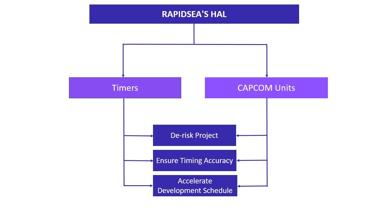
We believe in empowering engineers to solve problems, not to rewrite drivers. Our RAPIDSEA Suite is built on this philosophy. At its core is a production-proven, robust HAL that provides a clean, portable API for timers, CAPCOM units, and a host of other peripherals. By leveraging RAPIDSEA's abstraction layer, you can de-risk your projects, ensure timing accuracy, and dramatically accelerate your development schedule, regardless of the underlying silicon.
- Learn more about the RAPIDSEA Suite
- Dive into our HAL documentation for Timers and CAPCOM: Timer Interface